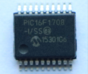
Readout PIC16F1708 Microchip Embedded Firmware
If interrupt priority is not used, all interrupts may use the fast register stack for returns from interrupt. If no inter- rupts are used when Readout PIC16F1708 Microchip Embedded Firmware, the fast register stack can be used to restore the STATUS, WREG and BSR registers at the end of a subroutine call.

To use the fast register stack for a subroutine call, a CALL label, FAST instruction must be executed to save the STATUS by Crack MCU, WREG and BSR registers to the fast register stack. A RETURN, FAST instruction is then executed to restore these registers from the fast register stack when Read MCU ATMEGA461A Software. Below example shows a source code example that uses the fast register stack during a subroutine call and return.

There may be programming situations that require the creation of data structures, or look-up tables, in program memory obtained from Read IC ATMEGA261A Program. For PIC16 devices, look-up tables can be implemented in two ways:
- Computed GOTO
- Table Reads
A computed GOTO is accomplished by adding an offset to the program counter. An example is shown in below Example.

A look-up table can be formed with an ADDWF PCL instruction and a group of RETLW nn instructions. The W register is loaded with an offset into the table before executing a call to that table in the process of Read Chip ATTINY88A Program. The first instruction of the called routine is the ADDWF PCL instruction by Readout PIC16F1708 Microchip Embedded Firmware. The next instruction executed will be one of the RETLW nn instructions that returns the value ‘nn’ to the calling function.
The offset value (in WREG) specifies the number of bytes that the program counter should advance and should be multiples of 2 (LSb = 0). In this method, only one data byte may be stored in each instruction location and room on the Return Address Stack is required in order to Read Microcontroller ATTINY88V Software.
.

