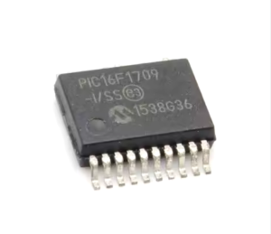
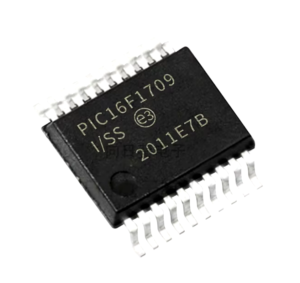
Read Microchip PIC16F1709 MCU flash program and eeprom software in the format of binary code or heximal data needs to unlock secured PIC16F1709 microcontroller tamper resistance system, extract embedded firmware from original encrypted microprocessor PIC16F1709;

Read Microchip PIC16F1709 MCU Flash Program needs to understand the A/D Acquisition Requirements. For the ADC to meet its specified accuracy, the charge holding capacitor (CHOLD) must be allowed to fully charge to the input channel voltage level.
The Analog Input model is shown in below Figure. The source impedance (RS) and the internal sampling switch (RSS) impedance directly affect the time required to charge the capacitor CHOLD to facilitate the process of Microprocessor PIC18F2420 Flash Content Reading. The sampling switch (RSS) impedance varies over the device voltage (VDD), refer to below Figure. The maximum recommended impedance for analog sources is 10 kW.

The Timer0 module is an 8-bit timer/counter with the following features:
8-bit timer/counter register (TMR0)
8-bit prescaler (independent of Watchdog Timer)
Programmable internal or external clock source
Programmable external clock edge selection
Interrupt on overflow to Extract MCU PIC18F2331 Code
TMR0 can be used to gate Timer1
The Timer0 module can be used as either an 8-bit timer or an 8-bit counter.
0.1 8-BIT TIMER MODE

The Timer0 module will increment every instruction cycle if Read Microchip PIC16F1709 MCU Flash Program, if used without a prescaler. 8-Bit Timer mode is selected by clearing the TMR0CS bit of the OPTION_REG register. When TMR0 is written, the increment is inhibited for two instruction cycles immediately following the write after MCU Crack.
The value written to the TMR0 register can be adjusted, in order to account for the two instruction cycle delay when TMR0 is written only after Copy Microcontroller PIC18F2410 Heximal.


