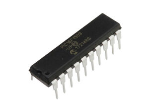
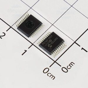
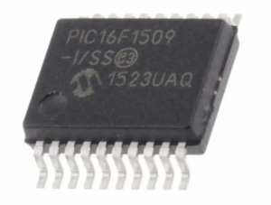
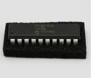
Reading a locked Microchip PIC16F1509 memory archive requires advanced techniques to crack or decode the encrypted firmware stored in the microcontroller’s flash memory and EEPROM memory. The PIC16F1509 MCU is designed with protective features to prevent unauthorized access to its binary, heximal, and program data, making it difficult to retrieve its source code or restore its software. However, through reverse engineering, these protections can be bypassed to unlock the memory and access the embedded data.

The process begins by analyzing the architecture of the microprocessor, identifying encryption and security measures that restrict access. By cracking the encrypted firmware, it becomes possible to read the program stored in the flash memory and EEPROM memory, allowing the retrieval of essential software or source code. This data can then be restored or cloned for use in similar devices or systems.
Once the memory is unlocked, the binary or heximal data can be copied, cloned, or replicated to create backup systems or repair malfunctioning equipment. For instance, if the original software is damaged or lost, reading the locked memory archive can provide the necessary data to restore the program’s functionality. Additionally, cloning the firmware can enable developers to duplicate the microcontroller’s capabilities for new applications.

Despite the technical feasibility of reading the locked Microchip PIC16F1509 memory archive, it is crucial to perform these actions within legal and ethical guidelines. Unauthorized access to secured microcontrollers can violate intellectual property laws, making it essential to ensure all reverse engineering efforts are conducted with proper permissions.
If we try to Read Locked Microchip PIC16F1509 Memory Archive, through signal transmission glitch can disable the protection mechanism and switch the mode of Microcontroller from locked to unlock status.
through the interruption we can have single shot mode, When the PWM time base is in the Single-Shot mode (PTMOD<1:0> = 01), an interrupt event is generated when a match with the PTPER register occurs. The PWM Time Base register (PTMR) is reset to zero on the following input clock edge and the PTEN bit is cleared. The postscaler selection bits have no effect in this Timer mode to faciliate the process of Read PIC16F874 Heximal Out Of Microcontroller.

In the Continuous Up/Down Count mode (PTMOD<1:0> = 10), an interrupt event is generated each time the value of the PTMR register becomes zero and the PWM time base begins to count upwards by MCU Cracking. The postscaler selection bits may be used in this Timer mode to reduce the frequency of the interrupt events. Below Figure shows the interrupts in Continuous Up/Down Count mode after Read Locked Microchip PIC16F1509 Memory Archive.
Interrupt in the double update mode is also quite commonly seen in this process, this mode is available in Continuous Up/Down Count mode. In the Double Update mode (PTMOD<1:0> =11), an interrupt event is generated each time the PTMR register is equal to zero and each time the PTMR matches the PTPER register to carry out the task of Copy Firmware Out Of Microchip PIC16F873. Figure 13-8 shows the interrupts in Continuous Up/Down Count mode with double updates. The Double Update mode provides two additional functions to the user in Center-Aligned mode.


