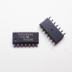
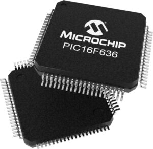
Read IC PIC16F636 Flash program and Eeprom data out and download the firmware to other blank MCU PIC16F636, microcontroller reverse engineering technique include microcomputer decapsulation, microprocessor delayer and focus ion beam cutting;

The Timer1 module is a 16-bit incrementing counter which is accessed through the TMR1H:TMR1L register pair. Writes to TMR1H or TMR1L directly update the counter. When used with an internal clock source, the module is a timer. When used with an external clock source, the module can be used as either a timer or counter if mcu attiny13a heximal reading.
The TMR1CS bit of the T1CON register is used to select the clock source. When TMR1CS = 0, the clock source is FOSC/4. When TMR1CS = 1, the clock source is supplied externally.
When the internal clock source is selected the TMR1H:TMR1L register pair will increment on multiples oscillator is enabled. RA5 and RA4 bits read as ‘0’ and TRISA5 and TRISA4 bits read as ‘1’. of FOSC as determined by the Timer1 prescaler.
When the external clock source is selected, the Timer1 module may work as a timer or a counter. When counting, Timer1 is incremented on the rising edge of the external clock input T1CKI.
In addition, the Counter mode clock can be synchronized to the microcontroller system clock or run asynchronously. If an external clock oscillator is needed (and the microcontroller is using the INTOSC without CLKOUT), Timer1 can use the LP oscillator as a clock source . Timer1 has four prescaler options allowing 1, 2, 4 or 8 divisions of the clock input. The T1CKPS bits of the T1CON register control the prescale counter. The prescale counter is not directly readable or writable;

however, the prescaler counter is cleared upon a write to TMR1H or TMR1L. A low-power 32.768 kHz crystal oscillator is built-in between pins OSC1 (input) and OSC2 (amplifier output). The oscillator is enabled by setting the T1OSCEN control bit of the T1CON register. The oscillator will continue to run during Sleep. The Timer1 oscillator is shared with the system LP oscillator.
Thus, Timer1 can use this mode only when the primary system clock is derived from the internal oscillator or when the oscillator is in the LP mode. The user must provide a software time delay to ensure proper oscillator start-up. TRISA5 and TRISA4 bits are set when the Timer1 oscillator is enabled. RA5 and RA4 bits read as ‘0’ and TRISA5 and TRISA4 bits read as ‘1’.

