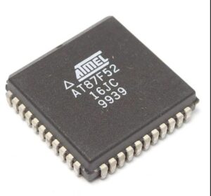
Read IC AT87F52 Firmware from its flash memory and eeprom memory after crack microcontroller at87f52 fuse bit:
The AT87F52 is a low-power, high-performance CMOS 8-bit microcomputer with 8K bytes of QuickFlash programmable read only memory. The device is manufactured using Atmel’s high density nonvolatile memory technology and is compatible with the industry standard 80C51 and 80C52 instruction set and pinout when Read IC.
The on-chip Quick-Flash allows the program memory to be user programmed by a conventional nonvolatile memory programmer. By combining a versatile 8-bit CPU with QuickFlash on a monolithic chip, the Atmel AT87F52 is a powerful microcomputer which provides a highly flexible and cost effective solution to many embedded control applications if Read IC.

Port 2 is an 8-bit bidirectional I/O port with internal pullups. The Port 2 output buffers can sink/source four TTL inputs. When 1s are written to Port 2 pins, they are pulled high by the internal pullups and can be used as inputs. As inputs, Port 2 pins that are externally being pulled low will source current (IIL) because of the internal pullups before Read IC.
Port 2 emits the high-order address byte during fetches from external program memory and during accesses to external data memory that use 16-bit addresses (MOVX @ DPTR). In this application, Port 2 uses strong internal pullups when emitting 1s. During accesses to external data memory that use 8-bit addresses (MOVX @ RI), Port 2 emits the contents of the P2 Special Function Register after Read IC.
Port 2 also receives the high-order address bits and some control signals during QuickFlash programming and verification. Timer 2 is selected as the baud rate generator by setting TCLK and/or RCLK in T2CON (Table 2). Note that the baud rates for transmit and receive can be different if Timer 2 is used for the receiver or transmitter and Timer 1 is used for the other function if Read IC.
Setting RCLK and/or TCLK puts Timer 2 into its baud rate generator mode, as shown in Figure 4. The baud rate generator mode is similar to the auto-reload mode, in that a rollover in TH2 causes the Timer 2 registers to be reloaded with the 16-bit value in registers RCAP2H and RCAP2L, which are preset by software.
The baud rates in Modes 1 and 3 are determined by Timer 2’s overflow rate according to the following equation. where (RCAP2H, RCAP2L) is the content of RCAP2H and RCAP2L taken as a 16-bit unsigned integer. Timer 2 as a baud rate generator is shown in Figure 4.
This figure is valid only if RCLK or TCLK = 1 in T2CON. Note that a rollover in TH2 does not set TF2 and will not generate an interrupt. Note too, that if EXEN2 is set, a 1-to-0 transition in T2EX will set EXF2 but will not cause a reload from (RCAP2H, RCAP2L) to (TH2, TL2). Thus when Timer 2 is in use as a baud rate generator, T2EX can be used as an extra external interrupt.
Note that when Timer 2 is running (TR2 = 1) as a timer in the baud rate generator mode, TH2 or TL2 should not be read from or written to. Under these conditions, the Timer is incremented every state time, and the results of a read or write may not be accurate. The RCAP2 registers may be read but should not be written to, because a write might overlap a reload and cause write and/or reload errors after Read IC.
The timer should be turned off (clear TR2) before accessing the Timer 2 or RCAP2 registers.

