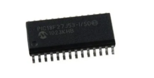
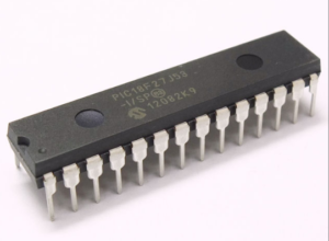
ICSP™ programming allows customers to manufacture circuit boards with unprogrammed devices when Extract MCU Method. Programming can be done after the assembly process allowing the device to be programmed with the most recent firmware or a custom firmware acquired by Microchip PIC18F27J53 Memory Source Code Extraction. Five pins are needed for ICSP™ programming:
- ICSPCLK
- ICSPDAT
- MCLR/VPP
- VDD
- VSS
In Program/Verify mode the program memory, user IDs and the Configuration Words are programmed through serial communications through Break IC Memory. The ICSPDAT pin is a bidirectional I/O used for transferring the serial data and the ICSPCLK pin is the clock input to Read MCU Software. For more information on ICSP™ refer to the “PIC16(L)F151X/152X Memory Programming Specification”, (DS41442).
The device is placed into High-Voltage Programming Entry mode by holding the ICSPCLK and ICSPDAT pins low then raising the voltage on MCLR/VPP to VIHH.
Some programmers produce VPP greater than VIHH (9.0V), an external circuit is required to limit the VPP voltage. See below Figure for example circuit.

The Low-Voltage Programming Entry mode allows the PIC16(L)F151X devices to be programmed using VDD only, without high voltage in case the process of Extract MCU AT89C51CC01 Code. When the LVP bit of Configuration Word 2 is set to ‘1’, the low-voltage ICSP programming entry is enabled. To disable the Low-Voltage ICSP mode, the LVP bit must be programmed to ‘0’.

Entry into the Low-Voltage Programming Entry mode requires the following steps:
- MCLR is brought to VIL.
- A 32-bit key sequence is presented on ICSPDAT, while clocking ICSPCLK.
Once the key sequence is complete, MCLR must be held at VIL for as long as Program/Verify mode is to be maintained. If low-voltage programming is enabled (LVP = 1), the MCLR Reset function is automatically enabled and cannot be disabled for the purpose of Extract IC AT89C5115 Code. The LVP bit can only be reprogrammed to ‘0’ by using the High-Voltage Programming mode.


