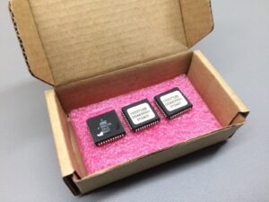
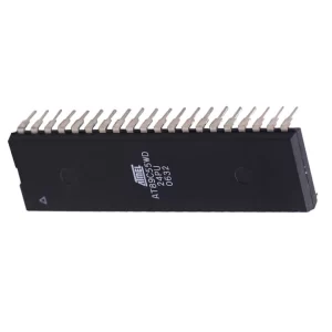
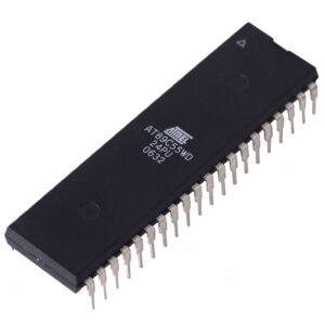
Extract Microcontroller AT89C55 Code starts from crack protective ATMEL MCU AT89C55 fuse bit and restore embedded firmware in the format of binary file or heximal data from encrypted microprocessor AT89C55 flash program memory and eeprom data memory;

The AT89C55 is a low-power, high-performance CMOS 8-bit microcomputer with 20K bytes of Flash programmable and erasable read only memory which is also the necessary step for Extract Microcontroller AT89C55 Code. The device is manufactured using Atmel’s high density nonvolatile memory technology and is compatible with the industry standard 80C51 instruction set and pinout.
The on-chip Flash allows the program memory to be reprogrammed in-system or by a conventional nonvolatile memory programmer. By combining a versatile 8-bit CPU with Flash on a monolithic chip, the Atmel AT89C55 is a powerful microcomputer which provides a highly flexible and cost effective solution to many embedded control applications.

The AT89C55 provides the following standard features: 20K bytes of Flash, 256-bytes of RAM, 32 I/O lines, three 16-bit timer/counters, a six-vector two-level interrupt architecture, a full duplex serial port, on-chip oscillator, and clock circuitry after Read Locked Microprocessor PIC18F2539 Source Code. In addition, the AT89C55 is designed with static logic for operation down to zero frequency and supports two software selectable power saving modes before Extract Microcontroller AT89C55 Code.
The Idle Mode stops the CPU while allowing the RAM, timer/counters, serial port, and interrupt system to continue functioning. The Power Down Mode saves the RAM contents but freezes the oscillator, disabling all other chip functions until the next hardware reset to facilitate the process of Copy Chip Protected PIC18F2550 Heximal. The low-voltage option saves power and operates with a 2.7-volt power supply.

Timer 0 and Timer 1 in the AT89C55 operate the same way as Timer) and Timer 1 in the AT89C51 and AT89C52. For further information, see the Microcontroller Data Book, section titled, “Timer/Counters.” Timer 2 is a 16 bit Timer/Counter that can operate as either a timer or an event counter. The type of operation is selected by bit C/T2 in the SFR T2CON before Secured MCU PIC18F2525 Heximal Reading.
Timer 2 has three operating modes: capture, auto-reload (up or down counting), and baud rate generator. The modes are selected by bits in T2CON, as shown in Table 3. Timer 2 consists of two 8-bit registers, TH2 and TL2. In the Timer function, the TL2 register is incremented every machine cycle. Since a machine cycle consists of 12 oscillator periods, the count rate is 1/12 of the oscillator frequency.
In the Counter function, the register is incremented in response to a 1-to-0 transition at its corresponding external input pin, T2. In this function, the external input is sampled during S5P2 of every machine cycle. When the samples show a high in one cycle and a low in the next cycle, the count is incremented in order to Extract Protected Microprocessor PIC18F2525 Code.

The new count value appears in the register during S3P1 of the cycle following the one in which the transition was detected. Since two machine cycles (24 oscillator periods) are required to recognize a 1-to-0 transition, the maximum count rate is 1/24 of the oscillator frequency before Extract Microcontroller AT89C55 Code.
To ensure that a given level is sampled at least once before it changes, the level should be held for at least one full machine cycle. In the capture mode, two options are selected by bit EXEN2 in T2CON. If EXEN2 = 0, Timer 2 is a 16 bit timer or counter which upon overflow sets bit TF2 in T2CON. This bit can then be used to generate an interrupt after Crack MCU.
If EXEN2 = 1, Timer 2 performs the same operation, but a 1 to-0 transition at external input T2EX also causes the current value in TH2 and TL2 to be captured into RCAP2H and RCAP2L, respectively. In addition, the transition at T2EX causes bit EXF2 in T2CON to be set. The EXF2 bit, like TF2, can generate an interrupt.

