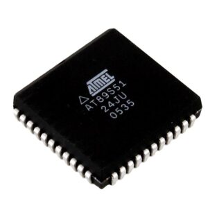
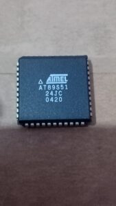
Extract IC AT89S51 Firmware from its flash and eeprom memory, disable the security fuse bit after decapsulate the microcontroller and crack MCU protective layers;
Extract IC AT89S51 Firmware: Unlocking the Protected Microcontroller
The AT89S51 is a widely used microcontroller (MCU) from Atmel, featuring flash memory and EEPROM storage. However, extracting its firmware can be challenging due to secured and encrypted protections. If you need to recover, copy, or replicate the program stored in this chip, specialized techniques such as attack, crack, and decrypt methods must be employed.

Understanding AT89S51 Firmware Protection
The AT89S51 microcontroller is designed with locked and protected memory regions to prevent unauthorized access. This security mechanism ensures the firmware or binary data remains secured from unauthorized copying or hacking attempts. However, when access is required for legitimate purposes, various techniques can be used to decode, decrypt, and extract the source code.

Ataque de desencapsulamento – Este processo envolve abrir fisicamente o pacote do chip para expor as estruturas internas. Usando feixe de íons focado (FIB) ou ataque ácido, áreas de memória protegidas podem ser acessadas para despejar dados.
Ataque de falha – Uma técnica de falha de voltagem ou clock pode ser usada para ignorar as proteções de segurança e extrair o arquivo de firmware da memória flash.
Despejo de EEPROM – Se o AT89S51 armazena dados em EEPROM, programadores especializados podem ser usados para ler e duplicar o conteúdo.
Engenharia reversa de firmware – Se o acesso parcial ao microcontrolador estiver disponível, a análise binária pode ajudar a descriptografar e decodificar o programa armazenado nele.
Techniques to Extract AT89S51 Firmware
Several methods exist to break through the locked or encrypted firmware and dump the data from the microprocessor:
-
Decapsulation Attack – This process involves physically opening the chip package to expose internal structures. By using focused ion beam (FIB) or acid etching, protected memory areas can be accessed for dumping data.
-
Glitch Attack – A voltage or clock glitching technique can be used to bypass security protections and extract the firmware file from the flash memory.
-
EEPROM Dumping – If the AT89S51 stores data in EEPROM, specialized programmers can be used to read and duplicate the content.
-
Firmware Reverse Engineering – If partial access to the microcontroller is available, binary analysis can help decrypt and decode the program stored within.
Conclusion
For those looking to recover or clone secured AT89S51 firmware, employing expert techniques such as breaking encryption, decrypting locked memory, or hacking protected flash files is necessary. Our specialized services offer reliable methods to dump, copy, and replicate the firmware from these microcontrollers efficiently.

Features
- Compatible with MCS-51® Products
- 4K Bytes of In-System Programmable (ISP) Flash Memory
– Endurance: 1000 Write/Erase Cycles
4.0V to 5.5V Operating Range
Fully Static Operation: 0 Hz to 33 MHz
Three-level Program Memory Lock 128 x 8-bit Internal RAM 32 Programmable I/O Lines
Two 16-bit Timer/Counters
Six Interrupt Sources
Full Duplex UART Serial Channel
Low-power Idle and Power-down Modes
Interrupt Recovery from Power-down Mode
Watchdog Timer after Extract microcontroller AT89C55 code
Dual Data Pointer
Power-off Flag
Fast Programming Time
Flexible ISP Programming (Byte and Page Mode)
Description
The AT89S51 is a low-power, high-performance CMOS 8-bit microcontroller with 4K bytes of in-system programmable Flash memory. The device is manufactured using Atmel’s high-density nonvolatile memory technology and is compatible with the industry-standard 80C51 instruction set and pinout.
The on-chip Flash allows the program memory to be reprogrammed in-system or by a conventional nonvolatile memory programmer. By combining a versatile 8-bit CPU with in-system programmable Flash on a monolithic chip, the Atmel AT89S51 is a powerful microcontroller which provides a highly-flexible and cost-effective solution to many embedded control applications before Extract chip firmware.
The AT89S51 provides the following standard features: 4K bytes of Flash, 128 bytes of RAM, 32 I/O lines, Watchdog timer, two data pointers, two 16-bit timer/counters, a five vector two-level interrupt architecture, a full duplex serial port, on-chip oscillator, and clock circuitry. In addition, the AT89S51 is designed with static logic for operation down to zero frequency and supports two software selectable power saving modes.
The Idle Mode stops the CPU while allowing the RAM, timer/counters, serial port, and interrupt system to continue functioning. The Power-down mode saves the RAM contents but freezes the oscillator, disabling all other chip functions until the next external interrupt or hardware reset.
To enable the WDT, a user must write 01EH and 0E1H in sequence to the WDTRST register (SFR location 0A6H). When the WDT is enabled, the user needs to service it by writing 01EH and 0E1H to WDTRST to avoid a WDT overflow. The 14-bit counter overflows when it reaches 16383 (3FFFH), and this will reset the device.
When the WDT is enabled, it will increment every machine cycle while the oscillator is running. This means the user must reset the WDT at least every 16383 machine cycles. To reset the WDT the user must write 01EH and 0E1H to WDTRST. WDTRST is a write-only register. The WDT counter cannot be read or written.
When WDT overflows, it will generate an output RESET pulse at the RST pin. The RESET pulse duration is 98xTOSC, where TOSC=1/FOSC. To make the best use of the WDT, it The WDT is intended as a recovery method in situations where the CPU may be subjected to software upsets. The WDT consists of a 14-bit counter and the Watchdog Timer Reset (WDTRST) SFR.
The WDT is defaulted to disable from exiting reset. To enable the WDT, a user must write 01EH and 0E1H in sequence to the WDTRST register (SFR location 0A6H). When the WDT is enabled, it will increment every machine cycle while the oscillator is running.
The WDT timeout period is dependent on the external clock frequency. There is no way to disable the WDT except through reset (either hardware reset or WDT overflow reset). When WDT overflows, it will drive an output RESET HIGH pulse at the RST pin.

