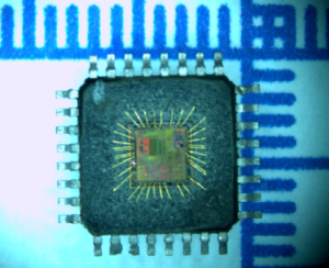
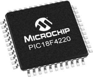
Extract Code of Protected Chip PIC18F4220 from flash and data memory after break mcu pic18f4220, the microcontroller pic18f4220 memory can be unlocked to reset the status and readout program and data;

If the IRCF bits and the INTSRC bit are all clear, the INTOSC output is not enabled and the IOFS bit will remain clear; there will be no indication of the current clock source. The INTRC source is providing the device clocks.
If the IRCF bits are changed from all clear (thus, enabling the INTOSC output) or if INTSRC is set, the IOFS bit becomes set after the INTOSC output becomes stable. Clocks to the device continue while the INTOSC source stabilizes after an interval of TIOBST when extract firmware of atmega8 mcu chip.
If the IRCF bits were previously at a non-zero value, or if INTSRC was set before setting SCS1 and the INTOSC source was already stable, the IOFS bit will remain set. On transitions from RC_RUN mode to PRI_RUN mode, the device continues to be clocked from the INTOSC multiplexer while the primary clock is started. When the primary clock becomes ready, a clock switch to the primary clock occurs (see Figure 3-4). When the clock switch is complete, the IOFS bit is cleared, the OSTS bit is set and the primary clock is providing the device clock.

The IDLEN and SCS bits are not affected by the switch. The INTRC source will continue to run if either the WDT or the Fail-Safe Clock Monitor is enabled.The Power Managed Sleep mode in the PIC18F4220 devices is identical to the legacy Sleep mode offered in all other PICmicro devices. It is entered by clearing the IDLEN bit (the default state on device Reset) and executing the SLEEP instruction. This shuts down the selected oscillator (Figure 3-5). All clock source status bits are cleared. Entering the Sleep mode from any other mode does not require a clock switch. This is because no clocks are needed once the controller has entered Sleep. If the WDT is selected, the INTRC source will continue to operate. If the Timer1 oscillator is enabled, it will also continue to run before MCU atmega16l heximal can be extracted.
When a wake event occurs in Sleep mode (by interrupt, Reset or WDT time-out), the device will not be clocked until the clock source selected by the SCS1:SCS0 bits becomes ready (see Figure 3-6), or it will be clocked from the internal oscillator block if either the Two-Speed Start-up or the Fail-Safe Clock Monitor are enabled (see Section 23.0 “Special Features of the CPU”). In either case, the OSTS bit is set when the primary clock is providing the device clocks. The IDLEN and SCS bits are not affected by the wake-up.

