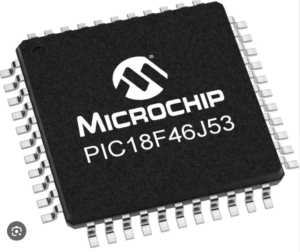
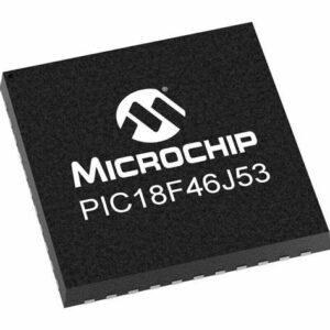
Copy PIC18F46J53 MCU source code needs to crack protective microcontroller PIC18F46J53 tamper resistance system and readout embedded firmware in the format of binary source code or heximal data file from secured MCU PIC18F46J53 flash memory and eeprom memory, the flash program which has been extracted from locked microprocessor PIC18F46J53 can be dumped to other new MCU;

Pin RA4 is multiplexed with the Timer0 module clock input and with an analog input to become the RA4/AN4/ T0CKI pin in the process of Copy PIC18F46J53 MCU Source Code. The RA4/AN4/T0CKI pin is a Schmitt Trigger input and full CMOS output driver.
Pin RA5 is multiplexed with the Master Clear module input which can help to Extract MCU PIC12C509A Code. The RA5/MCLR/VPP pin is a Schmitt Trigger input.

Pin RA6 is multiplexed with the oscillator module input and external oscillator output. Pin RA7 is multiplexed with the oscillator module input and external oscillator input.
Pin RA6/OSC2/CLKO and pin RA7/OSC1/CLKI are Schmitt Trigger inputs and full CMOS output drivers to Unlock Microcontroller.
Pins RA<1:0> are multiplexed with analog inputs. Pins RA<3:2> are multiplexed with analog inputs and VREF inputs. Pins RA<3:0> have TTL inputs and full CMOS output drivers from the lead of Extract MCU PIC12C508A Code.
PORTB is an 8-bit wide, bidirectional port. The corre- sponding data direction register is TRISB. Setting a TRISB bit (= 1) will make the corresponding PORTB pin an input and facilitate the process of Extract IC PIC16C57C Code, (i.e., put the corresponding output driver in a high-impedance mode).

Clearing a TRISB bit (= 0) will make the corresponding PORTB pin an output (i.e., put the contents of the output latch on the selected pin).
Each of the PORTB pins has a weak internal pull-up. A single control bit can turn on all the pull-ups. This is performed by clearing bit RBPU (OPTION_REG<7>). The weak pull-up is automatically turned off when the port pin is configured as an output in order to Copy PIC18F46J53 MCU Source Code. The pull-ups are disabled on a Power-on Reset.

Four of PORTB’s pins, RB7:RB4, have an interrupt-on- change feature. Only pins configured as inputs can cause this interrupt to occur (i.e., any RB7:RB4 pin configured as an output is excluded from the interrupt-on-change comparison). The input pins (of RB7:RB4) are compared with the old value latched on the last read of PORTB by Extract IC PIC16F54C Heximal,. The “mismatch” outputs of RB7:RB4 are ORed together to generate the RB Port Change Interrupt with Flag bit, RBIF (INTCON<0>).

