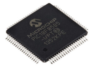
We can Copy Microprocessor PIC18F8585 Flash Memory, please view the Microprocessor PIC18F8585 features for your reference:
The TMR0 interrupt is generated when the TMR0 register overflows from FFh to 00h in 8-bit mode, or FFFFh to 0000h in 16-bit mode. This overflow sets the TMR0IF bit. The interrupt can be masked by clearing the TMR0IE bit in order to Extract MCU Microchip PIC16C622A Firmware. The TMR0IF bit must be cleared in software by the Timer0 module Interrupt Service Routine before re-enabling this interrupt.


The TMR0 interrupt cannot awaken the processor from Sleep mode, since the timer requires clock cycles even when T0CS is set. TMR0H is not the high byte of the timer/counter in 16-bit mode, but is actually a buffered version of the high byte of Timer0 (refer to below Figure).

The high byte of the Timer0 counter/timer is not directly readable nor writable. TMR0H is updated with the contents of the high byte of Timer0 during a read of TMR0L to facilitate the process of Copy Encrypted AVR MCU PIC16C621A. This provides the ability to read all 16 bits of Timer0 without having to verify that the read of the high and low byte were valid due to a rollover between successive reads of the high and low byte when Copy Microprocessor PIC18F8585 Flash Memory.
A write to the high byte of Timer0 must also take place through the TMR0H Buffer register in order . Timer0 high byte is updated with the contents of TMR0H when a write occurs to TMR0L by Cracking MCU. This allows all 16 bits of Timer0 to be updated at once.

The Timer1 timer/counter module has the following features:
- 16-bit timer/counter (two 8-bit registers; TMR1H and TMR1L)
- Readable and writable (both registers)
- Internal or external clock select
- Interrupt on overflow from FFFFh to 0000h
- Status of system clock operation
Figure 12-1 is a simplified block diagram of the Timer1 module after Read Microcontroller PIC16C620A Firmware.

