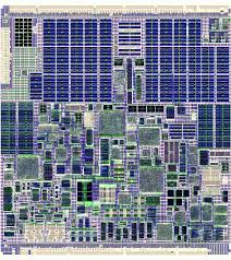
We can Copy Microcontroller PIC16C72A Code, please view the Microcontroller PIC16C72A features for your reference:
Timer mode is selected by clearing the T0CS bit (OPTION_REG<5>). In Timer mode, the Timer0 module will increment every instruction cycle (without prescaler). If TMR0 is written, the increment is inhibited for the following two instruction cycles when copy code from microcontroller.
The user can work around this by writing an adjusted value to the TMR0 register. Counter mode is selected by setting the T0CS bit (OPTION_REG<5>). In this mode, the Timer0 module will increment either on every rising or falling edge of pin RA4/C1OUT/T0CKI/SEG4 if microcontroller code can be copied.

The incrementing edge is determined by the source edge (T0SE) control bit (OPTION_REG<4>). Clearing the T0SE bit selects the rising code; A Timer0 interrupt is generated when the TMR0 register timer/counter overflows from FFh to 00h before copy code from micrcontroller.
This overflow sets the T0IF bit (INTCON<2>). The interrupt can be masked by clearing the T0IE bit (INTCON<5>). The T0IF bit must be cleared in software by the Timer0 module Interrupt Service Routine before re-enabling this interrupt copying.
The Timer0 interrupt cannot wake the processor from Sleep, since the timer is shut off during Sleep. When no prescaler is used, the external clock input is the same as the prescaler output. The synchronization of T0CKI, with the internal phase clocks, is accomplished by sampling the prescaler output on the Q2 and Q4 cycles of the internal phase clocks of microcontroller code.
Therefore, it is necessary for T0CKI to be high for at least 2 TOSC (and a small RC delay of 20 ns) and low for at least 2 TOSC (and a small RC delay of 20 ns). Refer to the electrical specification of the desired device. An 8-bit counter is available as a prescaler for the Timer0 module, or as a postscaler for the Watchdog Timer. For simplicity, this counter will be referred to as “prescaler” throughout this data sheet .
The prescaler assignment is controlled in software by the control bit PSA (OPTION_REG<3>). Clearing the PSA bit will assign the prescaler to Timer0. Prescale values are selectable via the PS<2:0> bits (OPTION_REG<2:0>). The prescaler is not readable or writable after microcontroller code has been copied.
When assigned to the Timer0 module, all instructions writing to the TMR0 register (e.g., CLRF 1, MOVWF 1, BSF 1, x….etc.) will clear the prescaler. When assigned to WDT, a CLRWDT instruction will clear the prescaler along with the Watchdog Timer of microcontroller copy.

