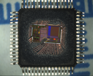
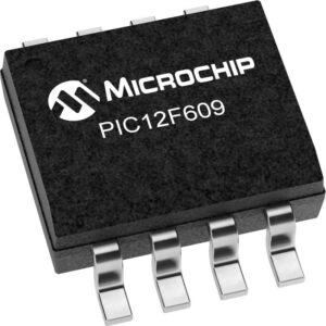
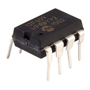
Copy Microcontroller PIC12F609 Firmware from embedded flash program memory, unlock the mcu pic12f609 protection system and breaking off pic12f609 security fuse bit;

The LTS and HTS bits of the OSCCON register will reflect the current active status of the LFINTOSC and HFINTOSC oscillators. The timing of a frequency selection is as follows if extract mcu by clock glitch method:
IRCF<2:0> bits of the OSCCON register are modified.
If the new clock is shut down, a clock start-up delay is started.
Clock switch circuitry waits for a falling edge of the current clock.
CLKOUT is held low and the clock switch circuitry waits for a rising edge in the new clock.
CLKOUT is now connected with the new clock.
LTS and HTS bits of the OSCCON register are updated as required.
Clock switch is complete.

See Figure 3-1 for more details.If the internal oscillator speed selected is between 8 MHz and 125 kHz, there is no start-up delay before the new frequency is selected. This is because the old and new frequencies are derived from the HFINTOSC via the postscaler and multiplexer when extract mcu at90s1200 code.
The system clock source can be switched between external and internal clock sources via software using the System Clock Select (SCS) bit of the OSCCON register.
The System Clock Select (SCS) bit of the OSCCON register selects the system clock source that is used for the CPU and peripherals.

- When the SCS bit of the OSCCON register = 0, the system clock source is determined by configuration of the FOSC<2:0> bits in the Configuration Word register (CONFIG).
- When the SCS bit of the OSCCON register = 1, the system clock source is chosen by the internal oscillator frequency selected by the IRCF<2:0> bits of the OSCCON register. After a Reset, the SCS bit of the OSCCON register is always cleared after read microcontroller attiny12 firmware.

