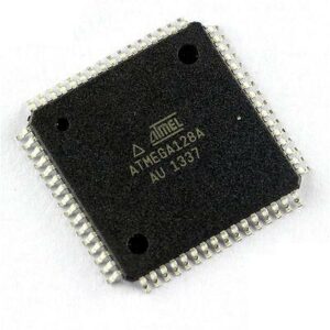
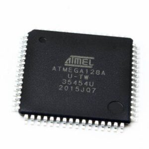
Copy ATMEL ATMEGA128A Encrypted Chip Flash Program starts from breaking off atmega128a mcu fuse bit and decipher microcontroller atmega128a avr flash memory code;

The ports are bi-directional I/O ports with optional internal pull-ups. Figure 22 on page 52 shows a functional description of one I/O port pin, here generically called Pxn.
Each port pin consists of 3 Register bits: DDxn, PORTxn, and PINxn. As shown in “Register Description for I/O Ports” on page 65, the DDxn bits are accessed at the DDRx I/O address, the PORTxn bits at the PORTx I/O address, and the PINxn bits at the PINx I/O address.

The DDxn bit in the DDRx Register selects the direction of this pin. If DDxn is written logic one, Pxn is configured as an output pin. If DDxn is written logic zero, Pxn is configured as an input pin by reading out atmega128a flash memory content.
If PORTxn is written logic one when the pin is configured as an input pin, the pull-up resistor is activated. To switch the pull-up resistor off, PORTxn has to be written logic zero or the pin has to be configured as an output pin. The port pins are tri-stated when a reset condition becomes active, even if no clocks are running.

If PORTxn is written logic one when the pin is configured as an output pin, the port pin is driven high (one) by reading mcu atmega128a chip flash memory data. If PORTxn is written logic zero to when the pin is configured as an output pin, the port pin is driven low (zero).

