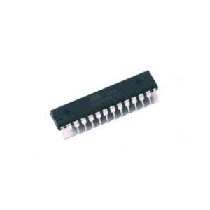
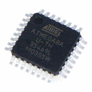
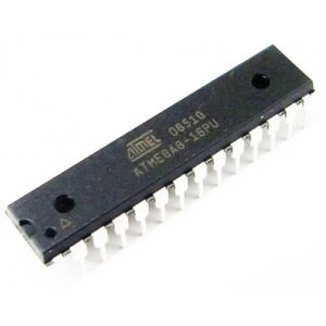
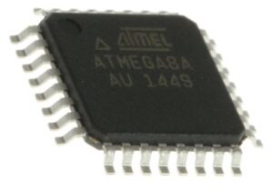
AVR Chip ATMEGA8A Binary Code Extraction needs to attack atmega8a secured MCU protection and dump flash heximal file out from atmega8a microcontroller flash memory;

For timing insensitive applications, the external RC configuration shown in Figure 12 on page 29 can be used. The frequency is roughly estimated by the equation f = 1/(3RC). C should be at least 22pF. By programming the CKOPT Fuse, the user can enable an internal 36pF capacitor between XTAL1 and GND, thereby removing the need for an external capacitor.
The Oscillator can operate in four different modes, each optimized for a specific frequency range. The operating mode is selected by the fuses CKSEL3..0 When this Oscillator is selected, start-up times are determined by the SUT Fuses as shown in Table 8.

The calibrated internal RC Oscillator provides a fixed 1.0MHz, 2.0MHz, 4.0MHz, or 8.0MHz clock. All frequencies are nominal values at 5V and 25°C. This clock may be selected as the system clock by programming the CKSEL Fuses as shown in Table 9. If selected, it will operate with no external components.
The CKOPT Fuse should always be unprogrammed when using this clock option. During reset, hardware loads the 1MHz calibration byte into the OSCCAL Reg- ister and thereby automatically calibrates the RC Oscillator. At 5V, 25°C and 1.0MHz Oscillator frequency selected, this calibration gives a frequency within ±3% of the nominal frequency.


Using run-time calibration methods as described in application notes available at www.atmel.com/avr it is possible to achieve ±1% accuracy at any given VCC and Temperature. When this Oscillator is used as the chip clock, the Watchdog Oscillator will still be used for the Watchdog Timer and for the Reset Time-out. For more information on the pre-programmed cali- bration value

