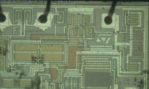
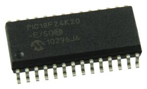
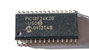
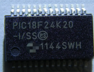
Secured Microchip MCU PIC18F24K20 Memory Code Readout needs to crack microcontroller pic18f24k20 protection and recover program and data from pic18f24k20 flash and eeprom memory;

When the Oscillator module is configured for LP, XT or HS modes, the Oscillator Start-up Timer (OST) counts 1024 oscillations from OSC1. This occurs following a Power-on Reset (POR) and when the Power-up Timer (PWRT) has expired (if configured), or a wake-up from Sleep.
During this time, the program counter does not increment and program execution is suspended. The OST ensures that the oscillator circuit, using a quartz crystal resonator or ceramic resonator, has started and is providing a stable system clock to the Oscillator module.

When switching between clock sources, a delay is required to allow the new clock to stabilize in order to readout software from encrypted microcontroller pic18f2680. These oscillator delays are shown in Table 2-1. In order to minimize latency between external oscillator start-up and code execution, the Two-Speed Clock Start-up mode can be selected (see Section 2.10 “Two-Speed Clock Start-up Mode”).
The LP, XT and HS modes support the use of quartz crystal resonators or ceramic resonators connected to OSC1 and OSC2 (Figure 2-3). The mode selects a low, medium or high gain setting of the internal inverter- amplifier to support various resonator types and speed.

LP Oscillator mode selects the lowest gain setting of the internal inverter-amplifier. LP mode current consumption is the least of the three modes. This mode is best suited to drive resonators with a low drive level specification, for example, tuning fork type crystals.
XT Oscillator mode selects the intermediate gain setting of the internal inverter-amplifier. XT mode current consumption is the medium of the three modes. This mode is best suited to drive resonators with a medium drive level specification.

HS Oscillator mode selects the highest gain setting of the internal inverter-amplifier. HS mode current consumption is the highest of the three modes. This mode is best suited for resonators that require a high drive setting.Figure 2-3 and Figure 2-4 show typical circuits for quartz crystal and ceramic resonators, respectively.

