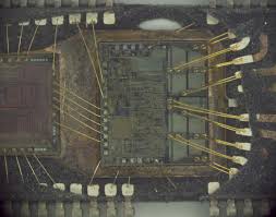
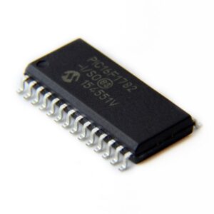
Read PIC16F1782 microcontroller flash program needs to crack secured microprocessor PIC16F1782 fuse bit, restore Microchip protective MCU PIC16F1782 flash memory and eeprom data memory embedded firmware of binary file or heximal source code;
A fetch cycle begins with the Program Counter (PC) incrementing in Q1 when Read PIC16F1782 Microcontroller Flash Program. In the execution cycle, the fetched instruction is latched into the Instruction Register (IR) in cycle Q1. This instruction is then decoded and executed during the Q2, Q3 and Q4 cycles. Data memory is read during Q2 (operand read) and written during Q4 (destination write).
The program memory is addressed in bytes. Instruc- tions are stored as two bytes or four bytes in program memory. The Least Significant Byte of an instruction word is always stored in a program memory location with an even address (LSb = 0) to Extract Microcontroller ATMEGA16L Heximal. To maintain alignment with instruction boundaries, the PC increments in steps of 2 and the LSb will always read ‘0’.
Below Figure shows an example of how instruction words are stored in the program memory.
The CALL and GOTO instructions have the absolute pro- gram memory address embedded into the instruction. Since instructions are always stored on word bound- aries, the data contained in the instruction is a word address. The word address is written to PC<20:1>, which accesses the desired byte address in program memory to support Extract Chip ATMEGA8L Firmware. Instruction #2 in above Figure shows how the instruction GOTO 0006h is encoded in the program memory acquired from Unlock Microcontroller.
Program branch instructions, which encode a relative address offset, operate in the same manner. The offset value stored in a branch instruction represents the number of single-word instructions that the PC will be offset by Extract IC ATMEGA8 Code. Section 24.0 “Instruction Set Summary” provides further details of the instruction set.
