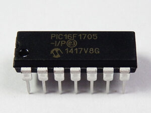
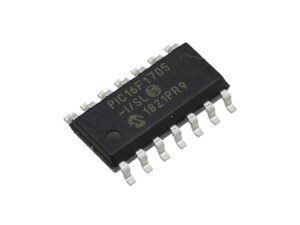
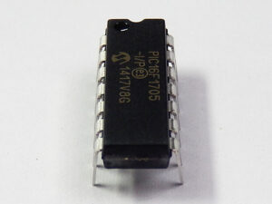
Microchip MCU PIC16F1705 embedded firmware extraction is a process starts from break off secured microcontroller PIC16F1705 fuse bit, restore embedded firmware from protective microprocessor PIC16F1705 flash program memory and eeprom data memory in the format of binary code or heximal file;

Effectively manipulate the analog to digital convertor module is one of the method for Microchip MCU PIC16F1705 Embedded Firmware Extraction.
The Analog-to-Digital Converter (ADC) allows conversion of an analog input signal to a 10-bit binary representation of that signal. This device uses analog inputs, which are multiplexed into a single sample and hold circuit by Unlock Microcontroller. The output of the sample and hold is connected to the input of the converter.
The converter generates a 10-bit binary result via successive approximation and stores the conversion result into the ADC result registers (ADRESH:ADRESL register pair). Below Figure shows the block diagram of the ADC.

The ADC voltage reference is software selectable to be either internally generated or externally supplied after Microchip MCU PIC16F1705 Embedded Firmware Extraction.
The ADC can generate an interrupt upon completion of a conversion. This interrupt can be used to wake-up the device from Sleep.
When configuring and using the ADC the following functions must be considered:
Port configuration
Channel selection
ADC voltage reference selection
ADC conversion clock source
Interrupt control
Result formatting
The ADC can be used to convert both analog and digital signals to faciliate the process of MCU PIC18LF448 Heximal Copying. When converting analog signals, the I/O pin should be configured for analog by setting the associated TRIS and ANSEL bits. Refer to Section 12.0 “I/O Ports” for more information.

There are up to 30 channel selections available:
- AN<19:8, 4:0> pins (PIC16(L)F1516/8 only)
- AN<27:0> pins (PIC16(L)F1517/9 only)
- Temperature Indicator
- FVR (Fixed Voltage Reference) Output
Refer to Section 14.0 “Fixed Voltage Reference (FVR)” and Section 15.0 “Temperature Indicator Module” for more information on these channel selections. The CHS bits of the ADCON0 register determine which channel is connected to the sample and hold circuit to ease the process of Microcontroller PIC18LF458 Program Reading. When changing channels, a delay is required before starting the next conversion. Refer to Section 16.2 “ADC Operation” for more information.


