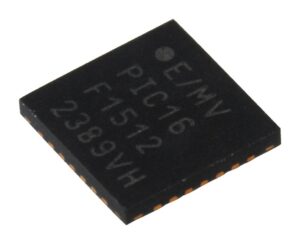
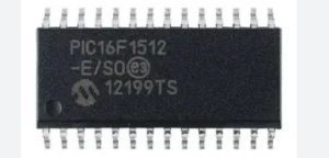
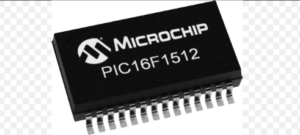
Protected Microchip PIC16F1512 MCU program copying involves advanced techniques to crack and decode the secured firmware stored within its flash memory and EEPROM memory. This microcontroller (MCU) is designed with protective features that encrypt its binary, heximal, and program data, ensuring that the embedded source code and software are locked against unauthorized access. However, through reverse engineering, it is possible to unlock the MCU’s encrypted memory for legitimate purposes such as system restoration, cloning, or program replication.

The process begins with a detailed analysis of the microprocessor’s architecture to bypass its protective barriers. By using specialized tools and techniques, engineers can decode the locked firmware, allowing access to critical program data stored within the flash and EEPROM memory. This is particularly useful in scenarios where the original program needs to be restored due to damage or where a clone of the software is required for replication in similar systems.
Once the secured memory is unlocked, the program can be extracted and analyzed to recover its source code. This enables the recreation of the firmware for use in repairing hardware, replicating devices, or adapting the program for new applications. The ability to copy a protective microcomputer’s program ensures that legacy systems relying on obsolete or discontinued MCUs remain functional.

While protected Microchip PIC16F1512 MCU program copying can provide valuable solutions, it must be performed responsibly, adhering to legal and ethical guidelines. Unauthorized cracking or cloning may violate intellectual property rights, making it essential to prioritize legitimate and ethical use cases.
In order to refurbish the electronic devices which has applied PIC16F1512 as its operation processor, it is necessary to have Protected Microchip PIC16F1512 MCU Program Copying and transfer this program to other blank PIC16F1512 unit, normally PWM will be used and play the power or signal glitch on it, one of the most important part of PWM mechanism is its period, The PWM period is defined by the PTPER register pair
(PTPERL and PTPERH).

The PWM period has 12-bit resolution by combining 4 LSBs of PTPERH and 8 bits of PTPERL. PTPER is a double-buffered register used to set the counting period for the PWM time base. The PTPER buffer contents are loaded into the PTPER register at the following times:
Free-Running and Single-Shot modes: When the PTMR register is reset to zero after a match with the PTPER register in order to Crack MCU.
Continuous Up/Down Count modes: When the PTMR register is zero. The value held in the PTPER buffer is automatically loaded into the PTPER register when the PWM time base is disabled (PTEN = 0) in order to Extract MCU PIC16C712 Firmware. Below Figure indicate the times when the contents of the PTPER buffer are loaded into the actual PTPER register.


