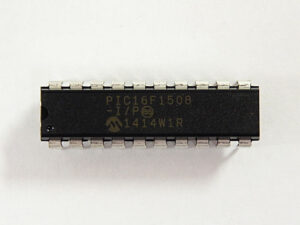
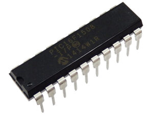
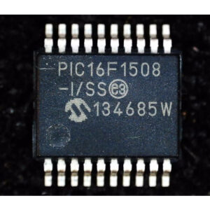
Reading microcontroller PIC16F1508 locked program involves cracking or decoding the secured and encrypted firmware stored in its flash memory and EEPROM memory. This microprocessor (MCU) is designed with protective mechanisms to prevent unauthorized access to its binary, heximal, and program data. To unlock the locked program, reverse engineering techniques are employed to bypass the encryption and retrieve the embedded software or source code.

The first step in reading the locked program from the PIC16F1508 is analyzing its microcontroller architecture. By identifying and breaking through its security features, technicians can access the encrypted firmware, which may contain crucial information about the program’s operation and functionality. Specialized tools are used to decode the firmware stored in the MCU’s memory, allowing the extraction of data from the flash memory and EEPROM memory.
Once the secured program is unlocked, the extracted firmware can be restored or cloned for various purposes. For example, the source code may be used to troubleshoot or replicate the original software for similar devices. Additionally, the ability to read the locked program is essential for system recovery in cases where the original data is lost, corrupted, or unavailable.

However, reading a microcontroller’s locked program must always be performed within legal and ethical guidelines. Unauthorized access to protected software or firmware can violate intellectual property rights, emphasizing the importance of securing proper authorization before engaging in such activities.
In summary, reading the microcontroller PIC16F1508 locked program involves cracking encrypted firmware and using reverse engineering techniques to unlock, decode, and recover essential software from the MCU’s flash and EEPROM memory.

Sometimes due to the product update requirement, we need to Read Microcontroller PIC16F1508 Locked Program out from its flash and eeprom area, manipulate its mode switch funtions precisely and flexible is critical to bypass the protection mechanism and get access to its databus. below we should introduce some of the most valuable and commonly used ones for your reference:
FIRST OF ALL is the FREE RUNNING MODE, In the Free-Running mode, the PWM time base (PTMRL and PTMRH) will begin counting upwards until the value in the PWM Time Base Period register, PTPER (PTPERL and PTPERH), is matched to Extract Microchip PIC12F752 Code. The PTMR registers will be reset on the following input clock edge and the time base will continue counting upwards as long as the PTEN bit remains set.
and then this is the SINGLE SHOT MODE, In the Single-Shot mode, the PWM time base will begin counting upwards when the PTEN bit is set. When the value in the PTMR register matches the PTPER register to achieve the execution of Copy Microchip PIC16F527 Heximal, the PTMR register will be reset on the following input clock edge and the PTEN bit will be cleared by the hardware to halt the time base.

the last one is CONTINUOUS UP/DOWN COUNT MODES, In Continuous Up/Down Count modes, the PWM time base counts upwards until the value in the PTPER register matches the PTMR register. On the following input clock edge, the timer counts downwards by Read Microchip MCU PIC12F519 Code. The PTDIR bit in the PTCON1 register is read-only and indicates the counting direction. The PTDIR bit is set when the timer counts downwards.
Since the PWM compare outputs are driven to the active state when the PWM time-base is counting downwards and matches the duty cycle value, the PWM outputs are held inactive during the first half of the first period of the Continuous Up/Down Count mode until the PTMR begins to count down from the PTPER value for the purpose of MCU Cracking.

