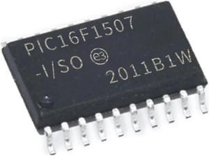
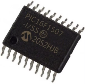
Extracting Microchip PIC16F1507 embedded code involves cracking the encrypted and locked firmware stored in the microcontroller’s flash memory and EEPROM memory. The protective MCU PIC16F1507 is designed with protective features to prevent unauthorized access to its binary and heximal data. However, reverse engineering techniques can be used to decode and unlock the secured PIC16F1507 microprocessor’s firmware for legitimate purposes, such as restoring functionality or replicating systems.

By analyzing the MCU’s architecture, experts can bypass the secured mechanisms protecting the firmware. Once unlocked, the embedded software, including the source code and program, can be restored or cloned for use in similar applications or to replace damaged systems. This process is particularly valuable when the original design files are unavailable or lost.
While extracting the embedded code from the PIC16F1507 can aid in system recovery or duplication, it must be done in compliance with ethical and legal standards to avoid violating intellectual property rights.

Extract Microchip PIC16F1507 Embedded Code means the firmware from both the eeprom and flash memory, in order to do that we need to have a general idea about the PWN module functionality, hereby we would like to discuss it:

The PWM module supports several modes of operation that are beneficial for specific power and motor control applications. Each mode of operation is described in subsequent sections to facilitate the progress of Read Microchip MCU PIC12F519 Code. The PWM module is composed of several functional blocks. The operation of each is explained separately in relation to the several modes of operation:
PWM Time Base
PWM Time Base Interrupts
PWM Period
PWM Duty Cycle
Dead-Time Generators
PWM Output Overrides
PWM Fault Inputs
PWM Special Event Trigger
regarding the PWM time base, which is provided by a 12-bit timer with prescaler and postscaler functions from Extract Microchip PIC16F1507 Embedded Code. A simplified block diagram of the PWM time base is shown in below Figure. The PWM time base is configured through the PTCON0 and PTCON1 registers by Crack MCU. The time base is enabled or disabled by respectively setting or clearing the PTEN bit in the PTCON1 register.

The PWM time base can be configured for four different modes of operation:
Free-Running mode
Single-Shot mode
Continuous Up/Down Count mode
Continuous Up/Down Count mode with interrupts
for double updates
These four modes are selected by the PTMOD1:PTMOD0 bits in the PTCON0 register. The Free-Running mode produces edge-aligned PWM generation. The Continuous Up/Down Count modes produce center-aligned PWM generation by Extract Microchip PIC12F752 Code. The Single-Shot mode allows the PWM module to support pulse control of certain Electronically Commutated Motors (ECMs) and produces edge-aligned operation.

