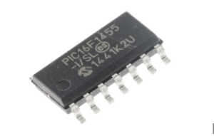
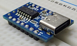
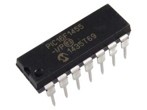
The PIC16F1455 is a popular microcontroller from Microchip, widely used in embedded systems for its compact design and efficient performance. However, when the memory is locked or secured, it can pose a challenge for developers, especially when trying to retrieve or modify the firmware. If the flash memory or EEPROM memory is encrypted or protected, it becomes increasingly difficult to access the source code or make necessary updates to the program.
When dealing with locked memory, the process of decrypting or extracting the contents can seem daunting. Techniques such as reverse engineering are often employed to attack the locked security measures. By using specialized tools and software, it’s possible to break or crack the encryption, although this often requires advanced knowledge of microprocessor architecture and low-level programming.
Recovering the locked heximal data or firmware involves using debugging tools that can decode the encrypted data. In many cases, decryption involves manipulating the program to bypass the security protocols or directly accessing the microcomputer’s memory via hardware-level interfaces.

It’s important to note that decrypting a secured microcontroller without proper authorization is illegal in many jurisdictions, as it may violate intellectual property rights and the software‘s licensing agreements. Therefore, before attempting to recover or decrypt the program, ensure you have the legal rights to access and modify the device.
In conclusion, while decrypting a locked PIC16F1455’s memory is possible through various methods like reverse engineering or using specific software tools, it requires significant technical expertise and careful consideration of the legal implications involved.
We can Decrypt Microcontroller PIC16F1455 Locked Memory, please view the Microcontroller PIC16F1455 features for your reference:

The TMR1 register pair (TMR1H:TMR1L) increments from 0000h to FFFFh and rolls over to 0000h. The Timer1 interrupt, if enabled, is generated on overflow which is latched in interrupt flag bit, TMR1IF (PIR1<0>). This interrupt can be enabled/disabled by setting/clearing Timer1 interrupt enable bit, TMR1IE (PIE1<0>).
Timer1 can be configured for 16-bit reads and writes. When the RD16 control bit (T1CON<7>) is set, the address for TMR1H is mapped to a buffer register for the high byte of Timer1 only after Copy MCU Microchip PIC16C77 Program. A read from TMR1L will load the contents of the high byte of Timer1 into the Timer1 High Byte Buffer register.

This provides the user with the ability to accurately read all 16 bits of Timer1 without having to determine whether a read of the high byte, followed by a read of the low byte, is valid due to a rollover between reads. A write to the high byte of Timer1 must also take place through the TMR1H Buffer register.

Timer1 high byte is updated with the contents of TMR1H when a write occurs to TMR1L. This allows a user to write all 16 bits to both the high and low bytes of Timer1 at once through Read Chip PIC16C76 Flash. The high byte of Timer1 is not directly readable or writable in this mode. All reads and writes must take place through the Timer1 High Byte Buffer register. Writes to TMR1H do not clear the Timer1 prescaler after Decrypt Microcontroller PIC16F1455 Locked Memory.
The prescaler is only cleared on writes to TMR1L. Adding an external LP oscillator to Timer1 (such as the one described in Section 12.2 “Timer1 Oscillator”), gives users the option to include RTC functionality to their applications only after Extract IC Microchip PIC16C74A Code.
This is accomplished with an inexpensive watch crystal to provide an accurate time base and several lines of application code to calculate the time to Crack MCU. When operating in Sleep mode and using a battery or super capacitor as a power source, it can completely eliminate the need for a separate RTC device and battery backup.

