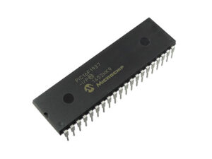
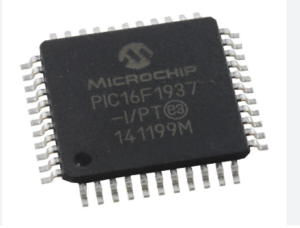
The PIC16F1937 microcontroller (MCU) is widely used in embedded systems due to its versatility and powerful features. However, its firmware is often read-protected to prevent unauthorized access, making it a prime target for hacking or reverse engineering attempts. A protected program or firmware can be secured through encryption, locking, or memory partitioning to ensure the integrity of sensitive data stored in the chip’s EEPROM or flash memory.

To attack a read-protected PIC16F1937 microcontroller, hackers might attempt to decapsulate the chip, removing its physical casing to access internal components. Once exposed, the attacker could try to dump the binary file from the MCU’s memory, extracting the source code or firmware. Using techniques like reverse engineering, they could attempt to decrypt or decode the encrypted data, bypassing protection mechanisms.

In more advanced cases, tools might be used to clone or replicate PIC16F1937 microcontroller’s behavior by recovering the original program. Techniques such as EEPROM extraction or memory manipulation can sometimes crack the secured system, allowing for unauthorized access or tampering with the code. However, these methods often require significant expertise and resources.
For engineers, securing the firmware of microcontrollers like the PIC16F1937 is essential to protect intellectual property and prevent malicious attacks that could compromise system functionality.
We can Read Protected Microcontroller PIC16F1937 Program, please view the Microcontroller PIC16F1937 features for your reference:
Timer1 can operate in one of these modes:
- As a timer
- As a synchronous counter
- As an asynchronous counter
The operating mode is determined by the Clock Select bit, TMR1CS (T1CON<1>).
When TMR1CS = 0, Timer1 increments every instruction cycle. When TMR1CS = 1, Timer1 increments on every rising edge of the external clock input or the Timer1 oscillator, if enabled only after Extract Microprocessor PIC16C72A Heximal.

When the Timer1 oscillator is enabled (T1OSCEN is set), the T1OSI and T1OSO/T1CKI pins become inputs. That is, the corresponding TRISA bit value is ignored, and the pins are read as ‘0’ by Crack MCU.
A crystal oscillator circuit is built-in between pins T1OSI (input) and T1OSO/TICKI (amplifier output). The placement of these pins depends on the value of Configuration bit, T1OSCMX (see Section 19.1 “Configuration Bits”). It is enabled by setting control bit T1OSCEN (T1CON<3>) before Read Protected Microcontroller PIC16F1937 Program.

The oscillator is a low-power oscillator rated for 32 kHz crystals. It will continue to run during all power-managed modes to facilitate the process of Read MCU PIC16C73B Eeprom. The circuit for a typical LP oscillator is shown in Figure 12-3. Table 12-1 shows the capacitor selection for the Timer1 oscillator. The user must provide a software time delay to ensure proper start-up of the Timer1 oscillator.

