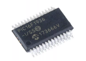
The PIC16F1937 microcontroller (MCU) is widely used in embedded systems due to its versatility and powerful features. However, its firmware is often read-protected to prevent unauthorized access, making it a prime target for hacking or reverse engineering attempts. A protected program or firmware can be secured through encryption, locking, or memory partitioning to ensure the integrity of sensitive data stored in the chip’s EEPROM or flash memory.

To attack a read-protected microcontroller, hackers might attempt to decapsulate the chip, removing its physical casing to access internal components. Once exposed, the attacker could try to dump the binary file from the MCU’s memory, extracting the source code or firmware. Using techniques like reverse engineering, they could attempt to decrypt or decode the encrypted data, bypassing protection mechanisms.
In more advanced cases, tools might be used to clone or replicate the microcontroller’s behavior by recovering the original program. Techniques such as EEPROM extraction or memory manipulation can sometimes crack the secured system, allowing for unauthorized access or tampering with the code. However, these methods often require significant expertise and resources.
For engineers, securing the firmware of microcontrollers like the PIC16F1937 is essential to protect intellectual property and prevent malicious attacks that could compromise system functionality.
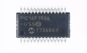
We can Extract MCU PIC16F1936 Heximal, please view the MCU PIC16F1936 features for your reference:
The Timer1 oscillator can be used as a secondary clock source in power-managed modes. When the T1RUN bit is set, the Timer1 oscillator provides the system clock. If the Fail-Safe Clock Monitor is enabled and the Timer1 oscillator fails while providing the system clock, polling the T1RUN bit will indicate whether the clock is being provided by the Timer1 oscillator or another source when Copy Encrypted AVR MCU PIC16C621A.

Timer1 can also be used to provide Real-Time Clock (RTC) functionality to applications with only a minimal addition of external components and code overhead from Crack MCU.
RD16: 16-Bit Read/Write Mode Enable bit
1 = Enables register read/write of Timer1 in one 16-bit operation
0 = Enables register read/write of Timer1 in two 8-bit operations
T1RUN: Timer1 System Clock Status bit
1 = Device clock is derived from Timer1 oscillator
0 = Device clock is derived from another source
T1CKPS1:T1CKPS0: Timer1 Input Clock Prescale Select bits

11 = 1:8 Prescale value
10 = 1:4 Prescale value
01 = 1:2 Prescale value
00 = 1:1 Prescale value
T1OSCEN: Timer1 Oscillator Enable bit
1 = Timer1 oscillator is enabled
0 = Timer1 oscillator is shut off
The oscillator inverter and feedback resistor are turned off to eliminate power drain in order to Read Microcontroller PIC16C620A Firmware.
T1SYNC: Timer1 External Clock Input Synchronization Select bit after Extract MCU PIC16F1936 Heximal
When TMR1CS = 1:
1 = Do not synchronize external clock input
0 = Synchronize external clock input

When TMR1CS = 0:
This bit is ignored. Timer1 uses the internal clock when TMR1CS = 0.
TMR1CS: Timer1 Clock Source Select bit
1 = External clock from T1OSO/T1CKI (on the rising edge)(1)
0 = Internal clock (FOSC/4)
TMR1ON: Timer1 On bit
1 = Enables Timer1
0 = Stops Timer1

