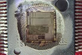
We can Read Code of Chip PIC18F8490 Flash, please view the Chip PIC18F8490 Features for your reference:
When the ECCP module is used in the PWM mode, the application hardware must use the proper external pullup and/or pull-down resistors on the PWM output pins. When the microcontroller is released from Reset, all of the I/O pins are in the high-impedance state. The external circuits must keep the power switch devices in the off state until the microcontroller drives the I/O pins with the proper signal levels, or activates the PWM output(s).

The CCP1M1:CCP1M0 bits (CCP1CON<1:0>) allow the user to choose whether the PWM output signals are active-high or active-low for each pair of PWM output pins (P1A/P1C and P1B/P1D). The PWM output polarities must be selected before the PWM pins are configured as outputs. Changing the polarity configuration while the PWM pins are configured as outputs is not recommended, since it may result in damage to the application circuits when read out the firmware from MCU.
The P1A, P1B, P1C and P1D output latches may not be in the proper states when the PWM module is initialized. Enabling the PWM pins for output at the same time as the ECCP module may cause damage to the application circuit. The ECCP module must be enabled in the proper output mode and complete a full PWM cycle before configuring the PWM pins as outputs. The completion of a full PWM cycle is indicated by the TMR2IF bit being set as the second PWM period begins if the microcontroller’s code can be read out.
The following steps should be taken when configuring the ECCP module for PWM operation:
- Configure the PWM pins, P1A and P1B (and P1C and P1D, if used), as inputs by setting the corresponding TRIS bits.
- Set the PWM period by loading the PR2 register.
- If auto-shutdown is required:
- Disable auto-shutdown (ECCP1AS = 0)
- Configure source (FLT0, Comparator 1 or
Comparator 2)
- Wait for non-shutdown condition
- Configure the ECCP module for the desired
PWM mode and configuration by loading the CCP1CON register with the appropriate values before IC’s software can be read:
-
- For Half-Bridge Output mode, set the dead-
- Set the PWM duty cycle by loading the CCPR1L
- Select the polarities of the PWM outputSelect one of the available outputconfigurations and direction with theP1M1:P1M0 bits to Crack MCU. signals with the CCP1M3:CCP1M0 bits. register and CCP1CON<5:4> bits.band delay by loading PWM1CON<6:0> with the appropriate value.
- Set the PWM duty cycle by loading the CCPR1L
-
- Wait until TMRn overflows (TMRnIF bit is set).
- Enable the CCP1/P1A, P1B, P1C and/or P1D
- Enable PWM outputs after a new PWM cycle
- Clear the TMR2 interrupt flag bit by clearing
- If auto-restart operation is required, set the
- Configure the comparator inputs as analog
- Set the ECCPASE bit (ECCP1AS<7>).
- Configure the comparators using the CMCON
- Select the shutdown states of the PWMIf auto-shutdown operation is required, load theECCP1AS register:
- Select the auto-shutdown sources using the
ECCPAS2:ECCPAS0 bits. output pins using the PSSAC1:PSSAC0 and
PSSBD1:PSSBD0 bits. register inputs. PRSEN bit (PWM1CON<7>).
- Select the auto-shutdown sources using the
- Select the shutdown states of the PWMIf auto-shutdown operation is required, load theECCP1AS register:
- Configure the comparator inputs as analog
- Configure and start TMR2: the TMR2IF bit (PIR1<1>).
- If auto-restart operation is required, set the
- Set the TMR2 prescale value by loading the
T2CKPS bits (T2CON<1:0>).
- Enable Timer2 by setting the TMR2ON bit
(T2CON<2>). has started: pin outputs by clearing the respective TRIS bits.
- Clear the TMR2 interrupt flag bit by clearing
- Enable PWM outputs after a new PWM cycle
- Clear the ECCPASE bit (ECCP1AS<7>).
- For Half-Bridge Output mode, set the dead-

